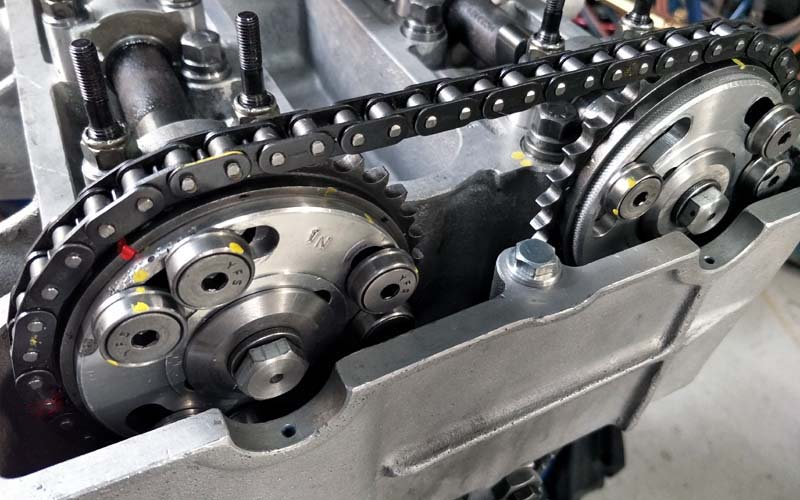
Convert Standard twin cam
sprockets to adjustable.
Trigger warning – This project is definitely for the serious DIY engineer – you’ll need access to a lathe and Milling machine plus the associated tooling.
Most people would understandably prefer to purchase ready made adjustable cam sprockets – But if you trust your engineering skills, and want to be proud of something you’ve made or built with your own hands, then this project is for you.
But, if you prefer to buy them off the shelf, then go for it.
Like most DIY projects, this one began many years ago during the initial planing stage, toying with the idea of building a tall block big twin cam lotus engine, it was going to be 1760cc capacity, but for reasons we wont go into here, we finally settled on 1700cc capacity. (And what an engine this turned out to be). But more on that for another time.
If you are familiar with the Twin Cam Lotus engine, you’ll know that setting the cam timing is very important, and becomes even more important if you move away from the standard parameters of the twin cam engine. In the past, fine adjustments to the cam timing settings are, or were made possible with off-set cam sprocket dowels. Now, if you’ve had experience with offset dowel pegs, they can be extremely time consuming and very fiddly to insert, remove, re-install for further or less offset, and then to check the timing…. well, my personal thoughts were —WAPITA these things are to work with.
You will quickly understand why the decision was made to build a set of adjustable cam sprockets.
So lets begin the journey.Text and pictures to follow, and I trust you will understand the process. What follows is really just a general overview of the build process, Hopefully it will make sense.
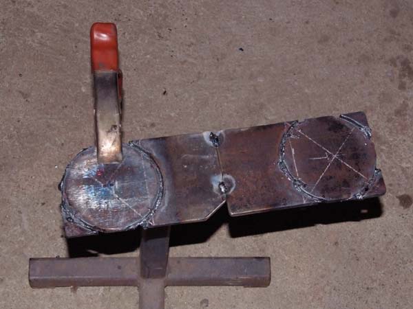
The beginning of the project.
Cutting the steel drive plates out of 5/16″ (8mm) thick MS plate with the gas axe (oxy torch). No, not a clean cut at all, so it will need a bit of grinding and cleaning up before any lathe machining begins.
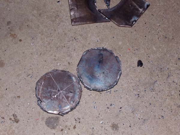
Oxy torch will generally provide a clean cut when flame is adjusted correctly, but sadly, that was not the case here.
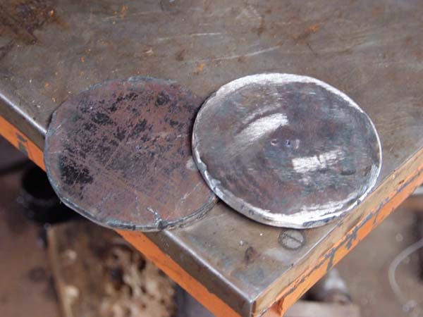
The plates (above), with oxy swarf and cutting dags removed ready for machining in the lathe. Now they need to carefully marked out with blue die and drilled for mounting on the old jack shaft (Cam shaft) which has the same hole PCD and spacing as the over head cams. A common PCD. The plates were cut from scrap mild steel plate found around the workshop, they are nothing special.
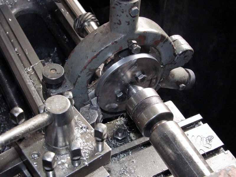
Now the fun begins, each drive plate is marked out, and drilled for mounting onto a dummy cam shaft, which is actually the original cross flow jack shaft that drives the distributor, oil and fuel pump. The picture shows the machining of the OD to near the required size. The keen observer will also note that all cam lobes have been removed, but that’s also another story, they were not required, so we removed them during one lazy Aussie Sunday afternoon.
Special Note: To carry out this project you will need an old camshaft (jack shaft), IE, the in block push-rod cam shaft, that all twin cams have, or obtain one from somewhere, it is an essential holding jig for the lathe work and machining to be done.
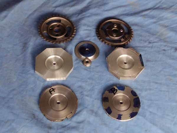
Photo above, Using the sprockets for layout drilling templates. Normally this would be all done on the milling machine and a rotary table, well, at that time we didn’t have a mill or rotary table, so it was back to old school layout methods. Note the little buttons inserted into the sprocket at top right, and the turned plate with a flange in the middle ground, use as an accurate drill jig. The aluminium plates are also part of the cam sprocket set up.
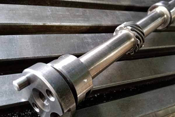
The bare (in block) jack-shaft, which has all of the cam lobes machined and ground off, excluding the fuel pump cam lobe. The tool post grinder was used to finish the shaft for a cleaner better engineering look. This camshaft may be altered again in the near future with timed flats milled (For con-rod clearance) into the shaft, that is if our plans for a 1.8 litre twink build should ever come to fruition, but that’s a long way down the track, just as the 1700 twink was way back in 2018-19, it was just an idea in my mind, but its now a reality, all complete and performing. (A brilliant project).
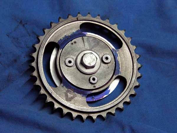
So if we combine the small dowels, the cam sprocket, and the plate that has a spigot machined to locate the centre sprocket hole, and the parts are secured with the bolt, an accurate PCD can be transferred to other parts using this method, yes, its old school, and takes a bit longer, but that’s OK, this is your play time, you’re not being charged $160.00+ per hour,
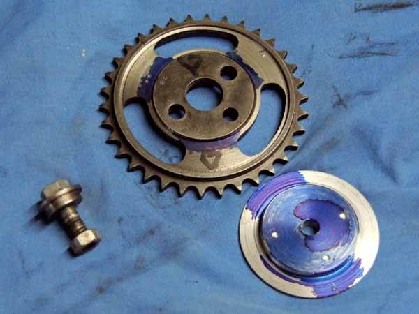
If we dismantle the cam sprocket and bits in the photo above, this is what we have. These parts are crucial to achieve drilling accuracy if you don’t have a milling machine and a rotary table, and all you have is a lathe.Study the image closely, and it will be all self explanatory. We did not include the small drilling jig buttons in the pic for some reason. The existing cam sprockets and cam shaft boss provide all of the dimensions required for this project.
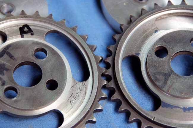
The external and internal face of the cam sprockets requires face machining to remove the rough casting surface to provide a very smooth clamp face. These faces are angled, and you will need to dial in the tool post to the required degree angle before the machining begins. The cam sprockets are mounted either on the cam shaft as shown in previous shots, or in a three or four jaw chuck arrangement.
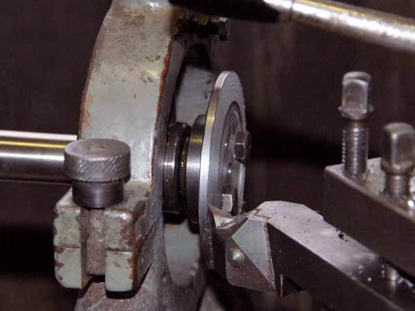
Sprocket drive plate face angle machining. Once the face angle of the sprockets has been determined, the exact same angle has to be machined on the drive plate, so that they match and mate perfectly together, if the angles do not match, the clamping force will be reduced when assembled, you don’t want any slippage after the engine has been built and running.
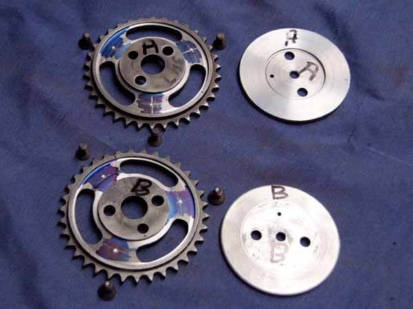
The cam sprockets and drive plates are fastened together with 1/4″ UNC countersunk screws (Three each) The sprockets are marked ready to drill where the blue layout die is on the spokes of the cam wheels.
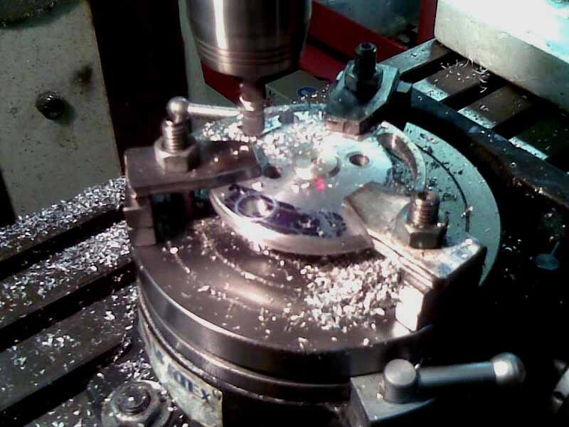
The aluminium plates are mounted and centered on the vertex index rotary table in order to mill the slots. The slots are of course where the screws and clamping nuts are inserted to advance or retard the cam timing. In other words, you use a crankshaft degree wheel in conjunction with a dial indicator to set the cams at the exact degree point that you wish the valves to open or close. You can not be that precise with fiddly and time consuming off-set dowel pins.
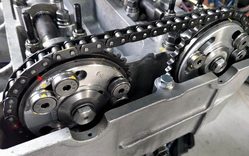
The picture opposite shows the adjustable cam sprockets assembled and installed. Note the milled radial slots in the aluminium plates, and the way the clamping screws are arranged.The assembly is neat and compact. The collars held by the 5/16″ UNC countersunk screws are machined from 4140, and the face has a protruding ring so that it grips on the aluminum, you don’t want them to slip and throw the cam timing out.
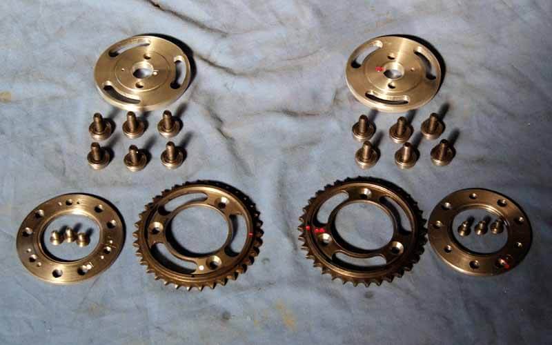
After all of the marking out, machining, trial fitting, and making sure that everything will clamp together and operate as required, the adjustable cam sprockets become a reality, and they can be fitted and used to dial in the camshafts to the crank degree required. I’m please to say that this pair of cam sprockets worked perfectly, and If I built another big twink, I would make another set, as I have no shortage of old cam sprockets.
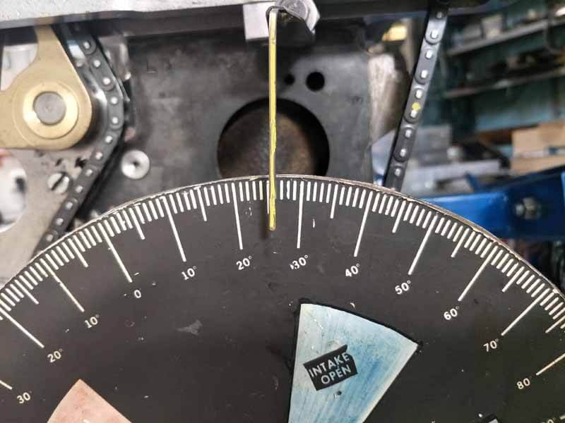
So, once you have the cylinder head with cams installed on the block, as part of the build, its wise to run a trial test and see how your work is going so far. You’ll need a degree plate mounted to the bolt on the crank shaft, plus a pointer securely mounted to the head or somewhere, the pointer here is a spoke out of a an old push bike wheel, and brazed to a metal bracket. Photo of the set up is for illustration purpose only.
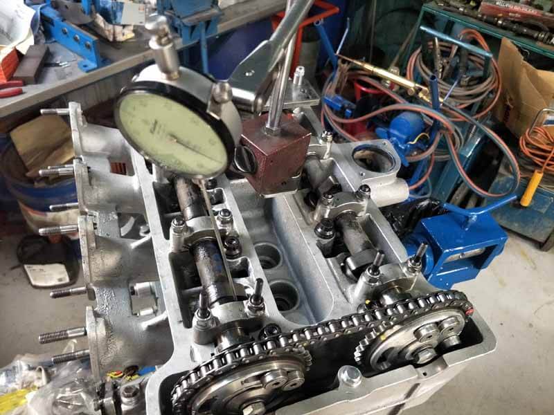
It is also essential to mount a dial test indicator with a long probe that can be made to rest on the exhaust or inlet valve bucket or follower, a short length of aluminium TIG welding rod works well because it can be screwed into the threads for two or three turns. The magnetic mounting base is sitting on a specially designed and fabricated MS platform which is secured temporarily by the cam cover bolts. It will take several attempts before you will be happy with the cam settings, but that’s the great advantage of adjustable cam sprockets. Once they are both dialed in, toque the screws or nuts up and that’s it, your’e done.
As we said at the beginning, this is not detailed, hold your hand how to build guide, but for the engineering inclined out there, you will most likely understand the process. Good luck and I hope you enjoyed the read and learning a bit more about the DIY engineering world.
Some might say, why spend all of that time making something when you could simply walk into a shop, or order online to obtain what you require. That may be true, but you’d be missing out on a hell of a DIY adventure.
Leave a Reply
You must be logged in to post a comment.