How To Pressure Test The TC Engine Block.
At long last, you’ve finally got around to the rebuilding of your twin cam engine?
With a pull down and dismantle, there are always plenty of parts to inspect, measure, and make notes about what to do during the rebuild.
One of the major items to check is to make sure the engine block is sound, IE, that it doesn’t leak anywhere, and the surest way to find that out is to carry out a pressure test, just to be sure.
When an engine becomes old and tired, you just never know what you may find when you make a detailed internal examination… I’m beginning to sound like a surgeon here.
If you are a keen DIY mechanic, you might like to do this work yourself, but you may not be one hundred percent sure of how to go about it.
You’ll be pleased to learn that the process is not that difficult to do… and the parts required can be DIY made or built for low cost in a reasonably well equipped home workshop.
Things You’ll Need For This Project:
- 1 x Air compressor – capable of delivering at least 60 to 80PSI.
- 1 x steel closing or sandwich plate to seal the top of the engine block.
- 1 x piece of 1/8″ thick insertion rubber (size to match sealing plate) to create the seal between the engine block and the top plate.
- 1 x closing plate to seal the water pump aperture.
- 1 x Piece insertion rubber as above.
- 1 x 1/4: BSPF Tap – 19 TPI.
- 1 x screw in air connector nipple – Rob from existing air tools.
- 1x pedestal or bench drill to drill holes in both closing plates.
- 10 x 1/4″ x 7/16″ UNC bolts – To fasten plate to engine block.
- 10 x 7/16″ Flat washers.
- 2 x 3/4″ x 1/4″ UNC bolts – To fasten water pump closing plate to block.
- 1 x 3/4″ x 5/16″ UNC bolt – To fasten water pump… Plus the usual tools and sundries required for a job like this in the workshop.
The first thing to make is the engine block top closing plate.
The measurements are taken from the engine block itself. The insertion rubber is also made the same size as the plate. You’ll find and purchase the sealing rubber at an Irrigation supply shop, it is used to make custom pipe sealing joints, and is quite cheap, other than that, a commercial rubber supply shop should have what you require.
To make the plate, grab on old head gasket, lay it on the plate, (make sure to orientate the gasket the correct way) mark with a texta marker where the holes are to be drilled… to be more accurate, apply some engineers marking out blue onto the steel plate, and place the head gasket on the plate and carefully scribe the outline of the head bolt holes… centre pop each hole, clamp the plate in the drill press, and using a small drill, drill all of the ten holes, drill as accurately as you can, because the pilot hole will determine where the next size up drill will go.
The head stud/bolts are 7/16″ Dia, but it is better to drill the holes in the plate oversize to allow some movement and extra clearance, as there is every chance you wont get all of the holes dead centre, unless the drilling work is being done in a milling machine with DRO settings.
The gasket can also be employed to mark out on the insertion rubber where the bolt holes need to be punched through with a wad punch… keeping in mind the correct orientation of the gasket to the block.
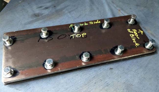
Drill holes as per head gasket dimensions – drill holes oversize.
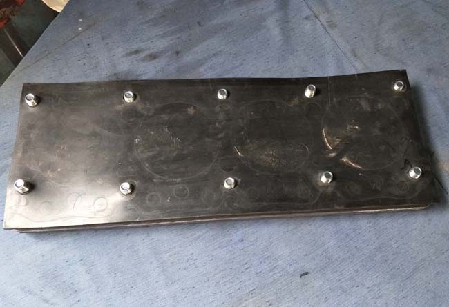
Bolt holes are marked out and punched through the rubber. When the plate and rubber seal are placed on top of the block, screw in all of the bolts, then tension as you would when tensioning cylinder head bolts. Start in the middle and work your way out. In the photo above the outline or impression of the cylinders can be clearly seen, so there was a lot of pressure applied, because you do not want any leaks here, or at the water pump closing plate during the test.

The bolts holes are marked out and clear drilled through the steel plate. A centre hole is drilled threaded in the plate, and holes punched through the rubber pad.
A 1/4″ BSPF (19TPI) threading tap is required so that a normal air fitting nipple can be screwed into the plate, which in turn will accept a push on air hose fitting/connector from the compressor, which in turn will apply the air pressure required for the pressure test.
I can understand if you may be thinking that this is all tool much work, and you’ll just let the engine shop do it all, well, that will be entirely your decision, the purpose of this article is to help those who want to save money, and wish to explore the process and learn new workshop procedures.
The entire process of drilling and threading of the steel plates, cutting and punching the rubber seals, and getting everything set up and in place only took about two hours… but once the plates have been made, the actual set up and testing time would only take about 30 mins.
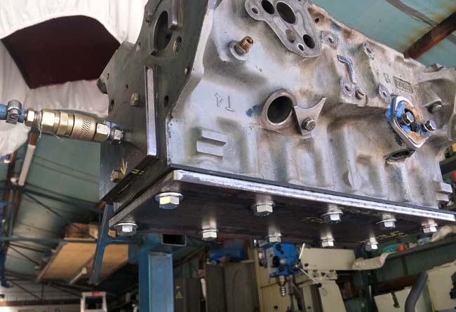
The very first test was carried out with just air pressure, with the block inverted and air pressure applied starting with about 25psi, then 40psi, then 60psi, we placed a rubber tube into each cylinder and just listened for air leaks that may have been coming through the cylinder walls.
The rubber hose trick is the same as what the old SU carby tuners employed to balance the air flow between each SU carburettor.
So after all four cylinders had been checked in this manner, the air hose was turned off, the line pressure released, it was time for the next test.
Leaving the engine block inverted, each cylinder was filled with soapy water, as the fluid is poured in it will create its own bubbles on the surface, but the rubber hose we just used can be also be used to blow air on the surface which will help to collapse the bubbles and eventually the surface will be clear.
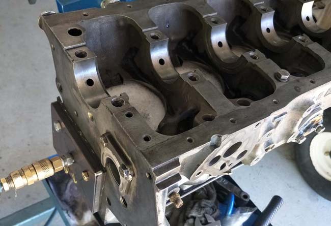
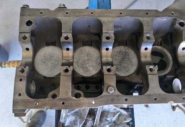
We were pleased to note that there were no air leaks, not even a very small leak in the block. Even with a slightly soapy froth on top of the water, if there is a leak in any of the cylinders, you will see the stream of air bubbles as they hit the surface.
Now that the block has been proven not to leak, it is time to move onto the next step, and take the block to the engine shop, and inform them that you have pressure tested the block… with an explanation of how you carried out the pressure test, and that’s another outgoing expense you wont have to pay, and you’ll now have the knowledge to do this again in the future, or you’ll be able to help a fellow enthusiast who wants to pressure test an engine block.
We hope this has been of help to you, and that you have learnt something useful.
This is elantrikbits sharing the knowledge with other lotus enthusiasts.
Leave a Reply
You must be logged in to post a comment.